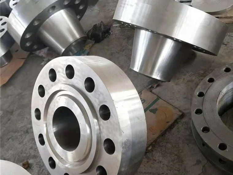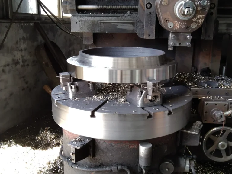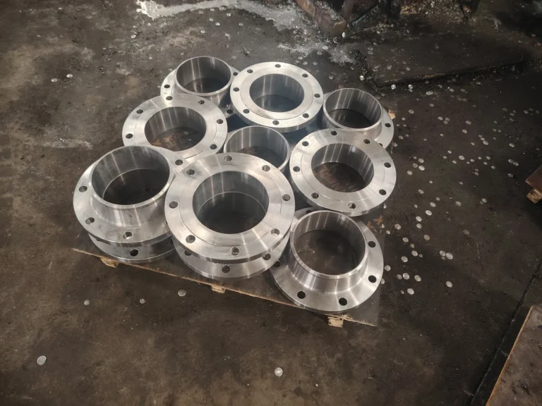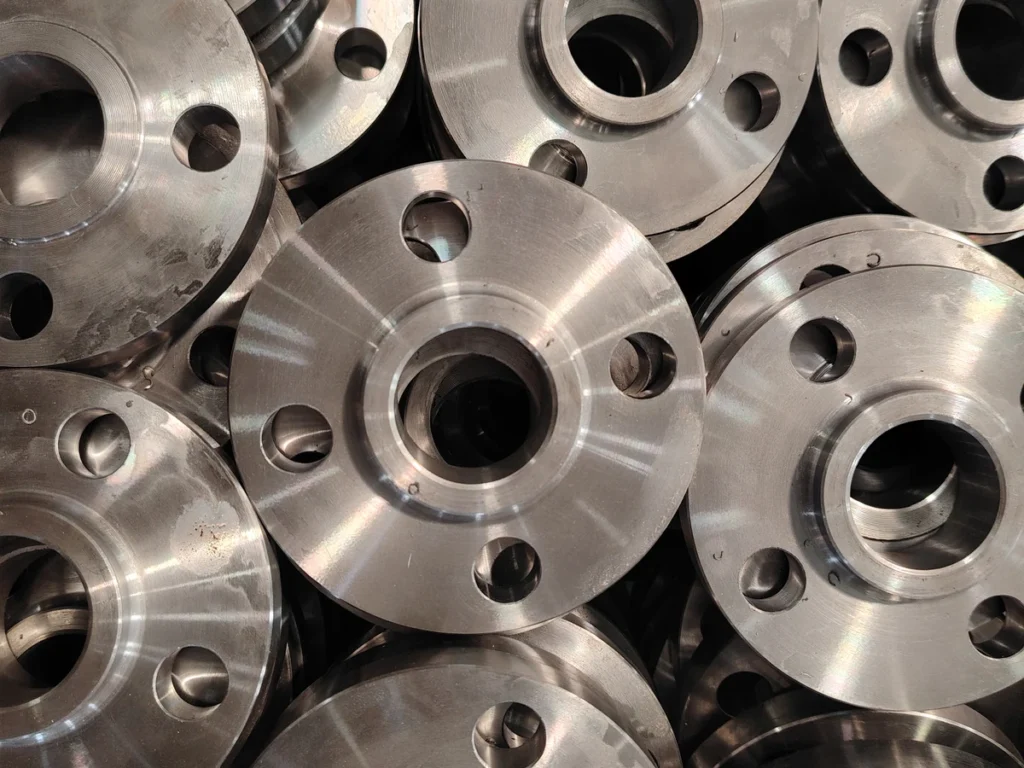
Pipe flanges form detachable connections between pipes, valves and equipment. Common types include weld neck, slip-on, socket weld, blind, threaded and lap joint flanges. Selection depends on the connection design, material, applicable standard, pressure-temperature rating and service conditions.
- What is a Flange?
A pipe flange provides a bolted connection to a compatible mating flange or equipment connection, usually with a gasket between the sealing faces. Depending on its design, the flange may be welded, threaded, used with a stub end, or integral with equipment. The joint requires compatible dimensions, materials, gasket and bolting.
The core value of a flanged connection lies in its “detachability.” Unlike welding, which is a permanent connection, flanged joints allow engineers to easily open sections of a system for maintenance, equipment replacement, pipeline cleaning, or process modification, and then reassemble it. This flexibility is crucial for the construction and operation of large-scale industrial facilities.
- Core Functions of Flanges
Connection and Sealing: This is the most fundamental and vital function. The bolt pre-load compresses the gasket, creating an effective seal to prevent the leakage of internal fluid (liquid or gas).
Facilitation of Maintenance and Inspection: Flanged joints provide access for localized maintenance after the system has been isolated, depressurized, drained or otherwise made safe under the site procedure. Do not loosen bolts on a live joint; dismantling and reassembly require an approved work procedure.
Structural Loads: A flanged joint must be checked for the pressure and external loads defined by the piping design. It does not replace the required pipe supports, restraints or flexibility assessment.
Adaptation to Complex Systems: They enable the convenient integration of pipes, equipment, and instruments (e.g., pressure gauges, flow meters) of different materials and specifications into a complete system.
- Main Types of Flanges
Depending on structure and connection method, various types of flanges have been developed to suit different pressures, temperatures, and applications.
Weld Neck Flange: Features a tapered hub and is butt-welded to the pipe. The tapered hub provides a transition to the pipe and is often specified for demanding service. Suitability for pressure, temperature, cyclic loading or hazardous media must follow the project design, material requirements and welding procedure.
Slip-On Flange: The pipe slides into the flange bore and is fillet welded both inside and outside. Installation and service suitability depend on the joint design. Do not infer a lower pressure rating from the flange type alone; check the applicable standard, material, class, temperature and piping-code restrictions, including cyclic-service requirements.
Socket Weld Flange: The pipe is inserted into a socket in the flange and then fillet welded. It is commonly considered for small-bore piping where the design permits. Confirm material, rating, weld preparation and any restrictions associated with cyclic loading or crevice-sensitive service.
Blind Flange: A solid disc with no bore. Its primary function is to blind off the end of a pipe or a nozzle, providing the potential for future system expansion. It acts as an “end cap” for pressure testing and system isolation.
Threaded Flange: The bore is threaded to connect directly with externally threaded pipes, requiring no welding. Use it only where the piping specification permits threaded joints, with the required thread form and pressure-temperature rating. Welding restrictions or galvanizing alone do not establish suitability.
Lap Joint Flange: Consists of a stub end and a loose backing flange. The flange ring can rotate freely, facilitating bolt hole alignment, which is particularly useful in space-restricted locations or for systems requiring frequent disassembly.
- Flange Standards and Pressure Ratings
Flange standards define requirements such as dimensions, materials, ratings and tolerances. Specify the full standard number, edition and applicable series; a shared nominal size or rating designation does not establish interchangeability across standards. Common references include:
American Standards: Represented by ASME B16.5 and ASME B16.47, widely used in the Americas and globally in the oil and gas industry.
European Standards: Represented by EN 1092-1, dominant in the European market.
Russian Standards: Confirm the exact GOST standard and edition required by the project, such as GOST 33259-2015 . Do not assume interchangeability with EN 1092-1. Check flange type, mating dimensions, bolt-hole pattern, facing, gasket, material and applicable rating requirements before accepting a substitution.
Chinese National Standards: The GB/T series, such as GB/T 9119.
Class and PN are rating designations, not interchangeable pressure values. Determine the allowable pressure from the applicable standard for the specified material and design temperature, and confirm that the mating components, gasket and bolting meet the joint requirements.
- Materials and Selection
The material of a flange directly determines its corrosion resistance, strength, and cost. Common materials include:
Carbon Steel: e.g., ASTM A105 (forging), A216 WCB (casting). Cost-effective, suitable for ambient temperatures and non-corrosive services.
Stainless Steel: e.g., ASTM A182 F304/F316. Offers good corrosion resistance and high-temperature strength, used in chemical, food, and pharmaceutical industries.
Alloy Steel: e.g., ASTM A182 F11/F22. Provides higher strength and better performance at elevated temperatures, used in power station boilers and high-temperature, high-pressure piping.
Special Alloys & Non-Metallics: e.g., Monel, Hastelloy, PVC, PP, used for highly corrosive services or special process requirements.
- Selection, Installation, and Maintenance Guide
Selecting the right flange requires considering factors like media characteristics, design pressure and temperature, connection standards, external loads, and cost.
Use the approved joint assembly procedure, with ASME PCC-1 where applicable. The following points are a checklist rather than a complete installation procedure:
Alignment: Ensure the two flange faces are parallel and centered, avoiding forced alignment.
Gasket Selection and Placement: Select the appropriate gasket material (e.g., non-asbestos, graphite, spiral-wound metal) based on the media and service conditions, and place it concentrically.
Bolt Tightening: Use the approved tightening method, sequence, passes and target bolt load or torque for the actual gasket, fasteners and lubrication condition. Use suitable calibrated tools and record the required assembly checks.
During maintenance, inspect for leakage and external corrosion according to the site plan. Inspect sealing faces during safe disassembly. Report leakage and follow the isolation and repair procedure; this overview does not authorize retightening a hot or pressurized joint.
Conclusion
For a flange quotation, provide the type, nominal size, material specification and grade, flange standard and edition, applicable series, pressure class or PN designation, facing and quantity. Include design pressure and temperature, service medium, mating pipe dimensions and bore where applicable, drawing revision, destination, and inspection or documentation requirements.