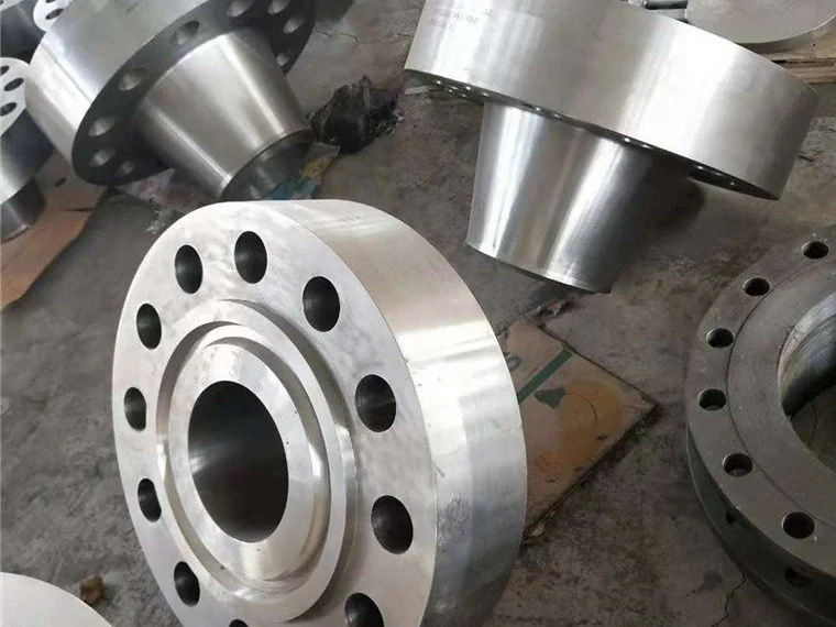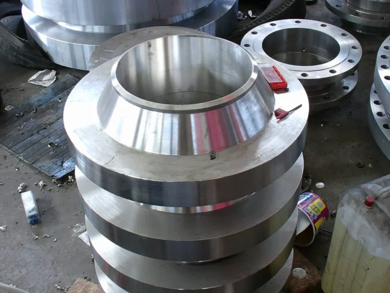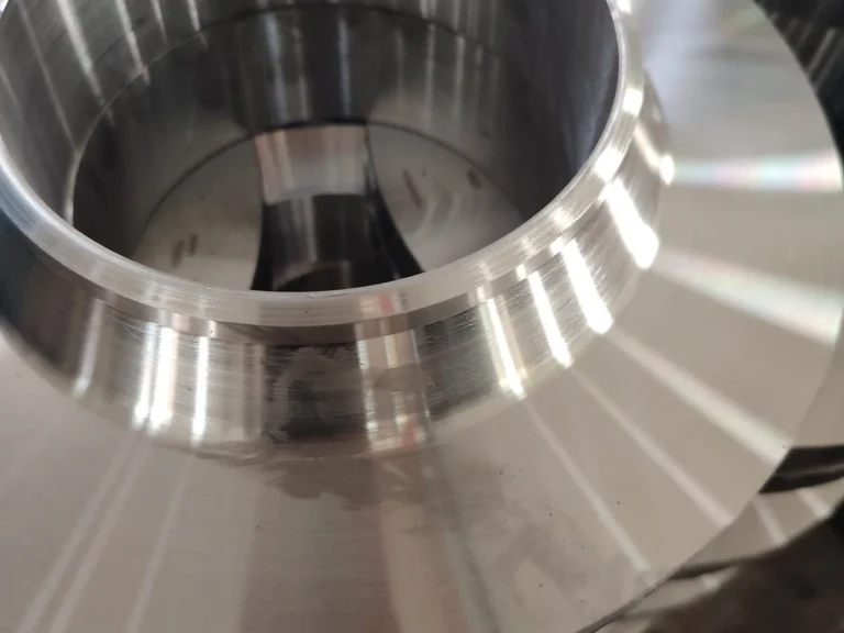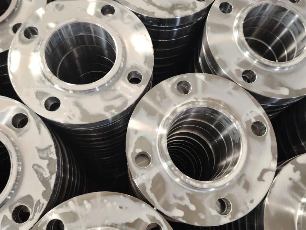
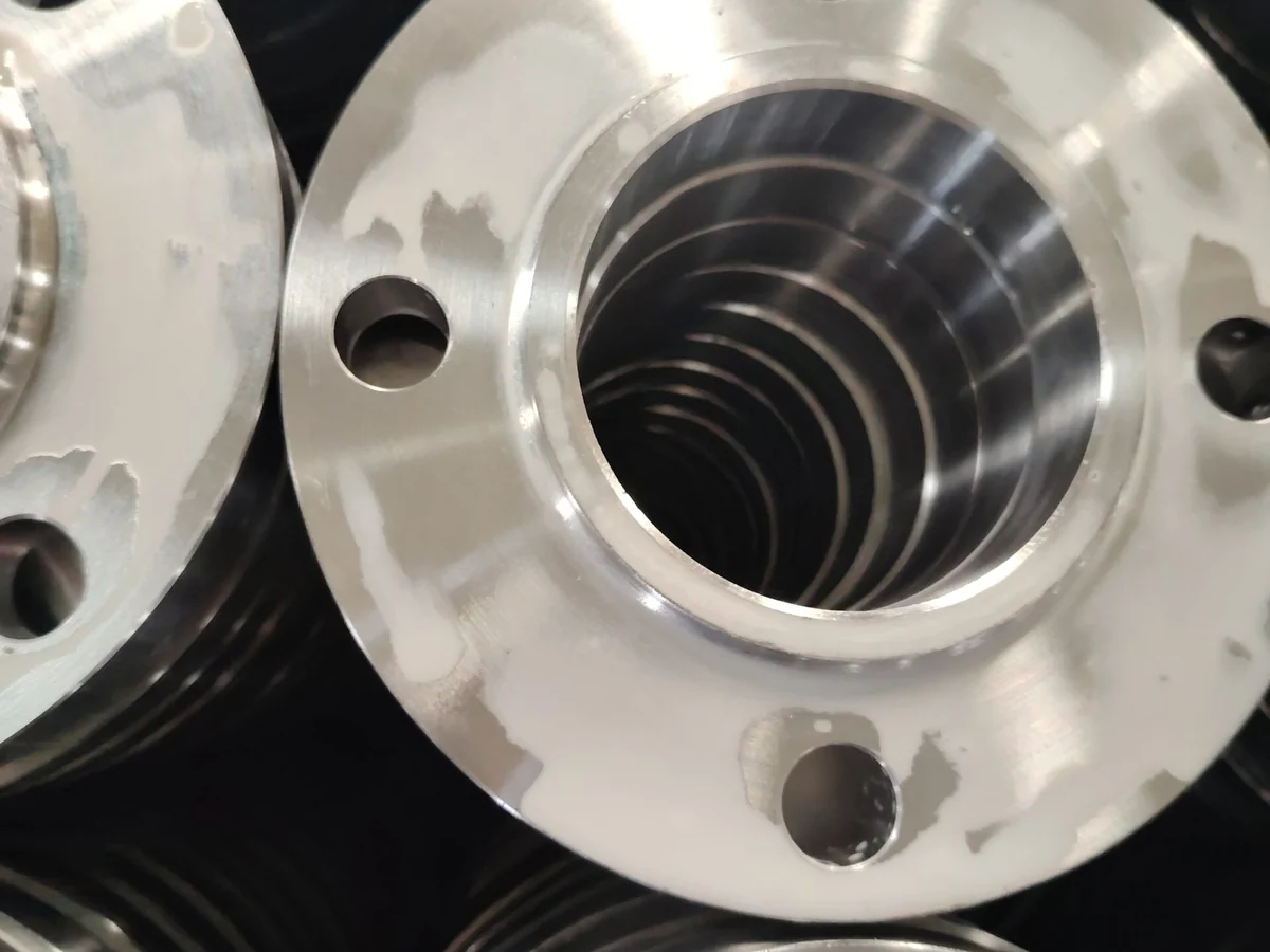
A slip-on flange fits over the outside of a pipe before it is welded in place. The pipe enters the flange bore, while the flange face provides the seating surface for the gasket.
This arrangement makes the bore an important dimension to check. The flange must fit over the pipe’s outside diameter; Check the slip-on flange bore against the pipe outside diameter and the dimensional tolerances specified in the applicable standards.
How the connection works
In a typical double-welded arrangement, fillet welds attach the flange at the hub end and on the inside near the flange face. The pipe end is positioned to allow the internal weld without interfering with the gasket seating surface.
The weld dimensions and pipe-end position should come from the applicable construction code and approved joint detail. They should not be taken from a product photograph or a general installation sketch. ASME B31.3 includes attachment-weld details for double-welded slip-on flanges, but the project requirements determine which details apply. ASME B31.3 contents.
The welds secure the flange to the pipe. The bolts bring the mating flanges together and load the gasket. The bolted connection can be dismantled while the flange remains welded to the pipe.
Why bore size matters
A slip-on flange bore fits around the pipe’s outside diameter. A weld neck flange connects at the end of its hub, where the welding-end geometry must suit the connected pipe.
For a slip-on flange, check the actual bore against the specified pipe outside diameter and the permitted fit-up clearance. A pipe schedule describes wall thickness under the relevant pipe dimensional standard; it should not be treated as a substitute for checking the slip-on bore.
The drawing should also show the pipe position relative to the flange face. Enough room is needed for the specified weld, while the gasket contact area must remain clear.
Reading a slip-on flange drawing
A useful dimensional review covers more than the flange outside diameter.
| Dimension | What to check |
|---|---|
| Flange outside diameter | Overall envelope and clearance |
| Bore diameter | Fit over the specified pipe |
| Flange thickness | Required thickness under the selected standard or drawing |
| Hub diameter and overall length | Connection geometry and available welding space |
| Bolt-circle diameter | Alignment with the mating flange |
| Bolt-hole size and quantity | Compatibility with the specified bolting |
| Facing dimensions | Compatibility with the gasket and mating face |
Dimension letters are drawing-specific. A symbol used for bore diameter on one drawing may mean something else on another.
The LeKe Piping slip-on flange product page includes a section drawing and product views for identifying these features. Use the drawing together with the applicable dimension table, rather than treating the illustration as a complete specification.
Standards and pressure ratings
ASME B16.5 covers pipe flanges and flanged fittings, including dimensions, materials, tolerances and pressure–temperature ratings. Its overall scope includes NPS ½ through NPS 24, with a smaller size range for Class 2500.
That overall scope is not a catalogue of every flange type in every size and class. For a slip-on flange, check the applicable type-specific provisions and tables in the specified edition. A general statement such as “ASME B16.5, Class 150–2500” does not establish that every slip-on configuration is covered. ASME B16.5 scope.
The same care is needed with large-diameter products. Confirm the standard and drawing that define the actual slip-on design instead of assuming that a large-diameter flange reference covers it.
Slip-on or weld neck?
The difference begins with the joint. A slip-on flange overlaps the pipe and uses an attachment-weld arrangement. A weld neck flange meets the pipe at a butt-welded connection.
This affects fabrication and inspection. Fillet welds do not offer the same access for volumetric examination as a suitably designed butt weld. TWI discusses these inspection limitations in its guidance on welded-joint design. TWI: Design—Part 3.
Selection therefore involves more than purchase price or pressure class. The piping specification, loading conditions, fluid service, inspection requirements and fabrication access all matter.
A fixed claim that one flange type lasts a certain number of times longer than another needs defined materials, joint details, loads and test conditions.
What to include in an enquiry
- Applicable standard and edition, or an approved drawing.
- Nominal size, pipe outside diameter and required flange bore.
- Pressure designation and facing.
- Material specification and grade.
- Quantity, inspection scope and required documents.
- Any special dimensions or machining requirements.
For a replacement, include the existing drawing where available. A photograph helps identify the general form, but it cannot establish the material, pressure rating or dimensional compatibility.
Send these details with your enquiry through the LeKe Piping slip-on flange page so the proposed supply can be checked against the actual connection requirements.