A weld neck flange has a tapered hub that is butt welded to the pipe. At the opposite end, bolts clamp two flange faces against a gasket. When specifying one, check the bore and welding end alongside the nominal size, pressure class and facing. This guide uses ASME B16.5 as its principal dimensional and rating reference.
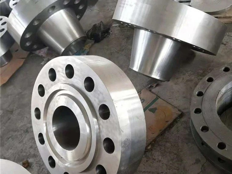
What Is a Weld Neck Flange?
A weld neck flange is also known as a welding neck flange or WN flange. Its hub narrows from the flange body to the welding end, where it joins the pipe or another compatible component. The circular body carries the bolt holes and sealing face.
The butt weld stays in place when the bolted joint is opened. This allows the connected equipment or pipe section to be separated without cutting the pipe-to-flange weld.
The Flange Body, Tapered Hub and Bore
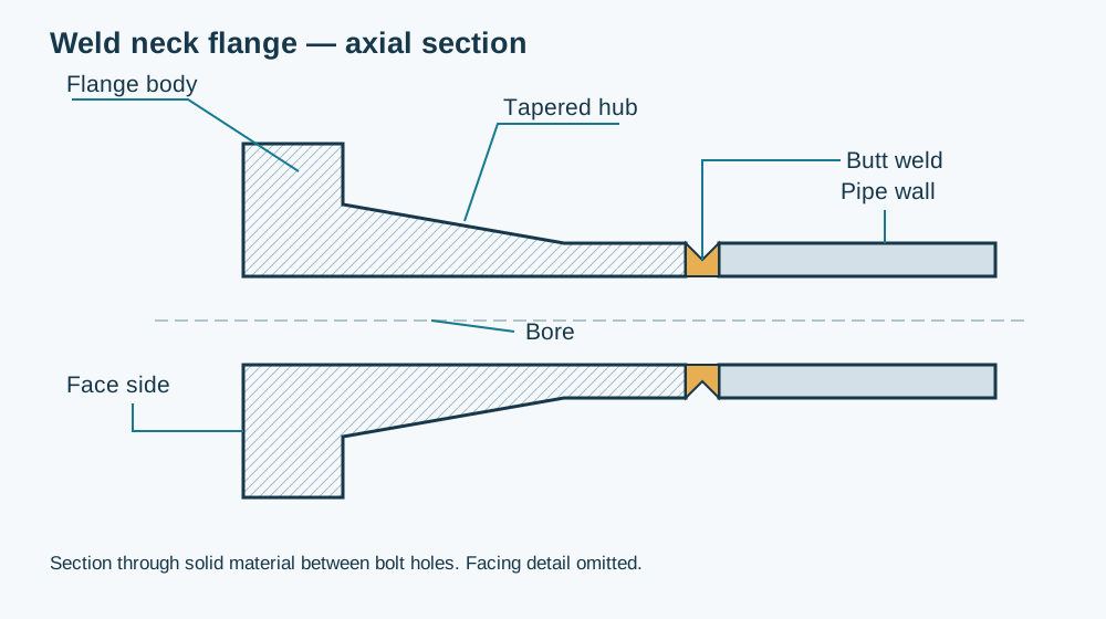
The flange body is the thick circular section containing the bolt holes. The tapered hub provides a gradual transition from this relatively stiff body to the pipe wall.
The bore runs through the body and hub. At the welding end, check its internal profile against the connected pipe and the specified joint detail. Where a transition is required, its shape belongs on the component drawing.
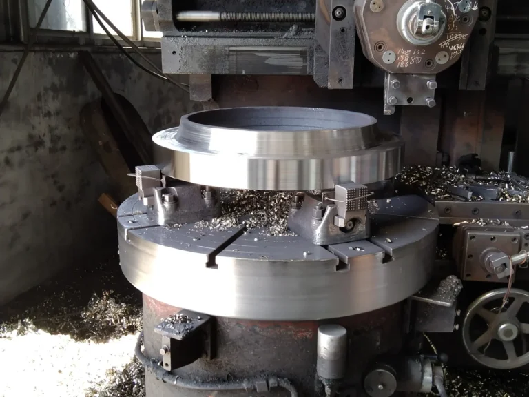
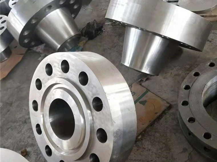
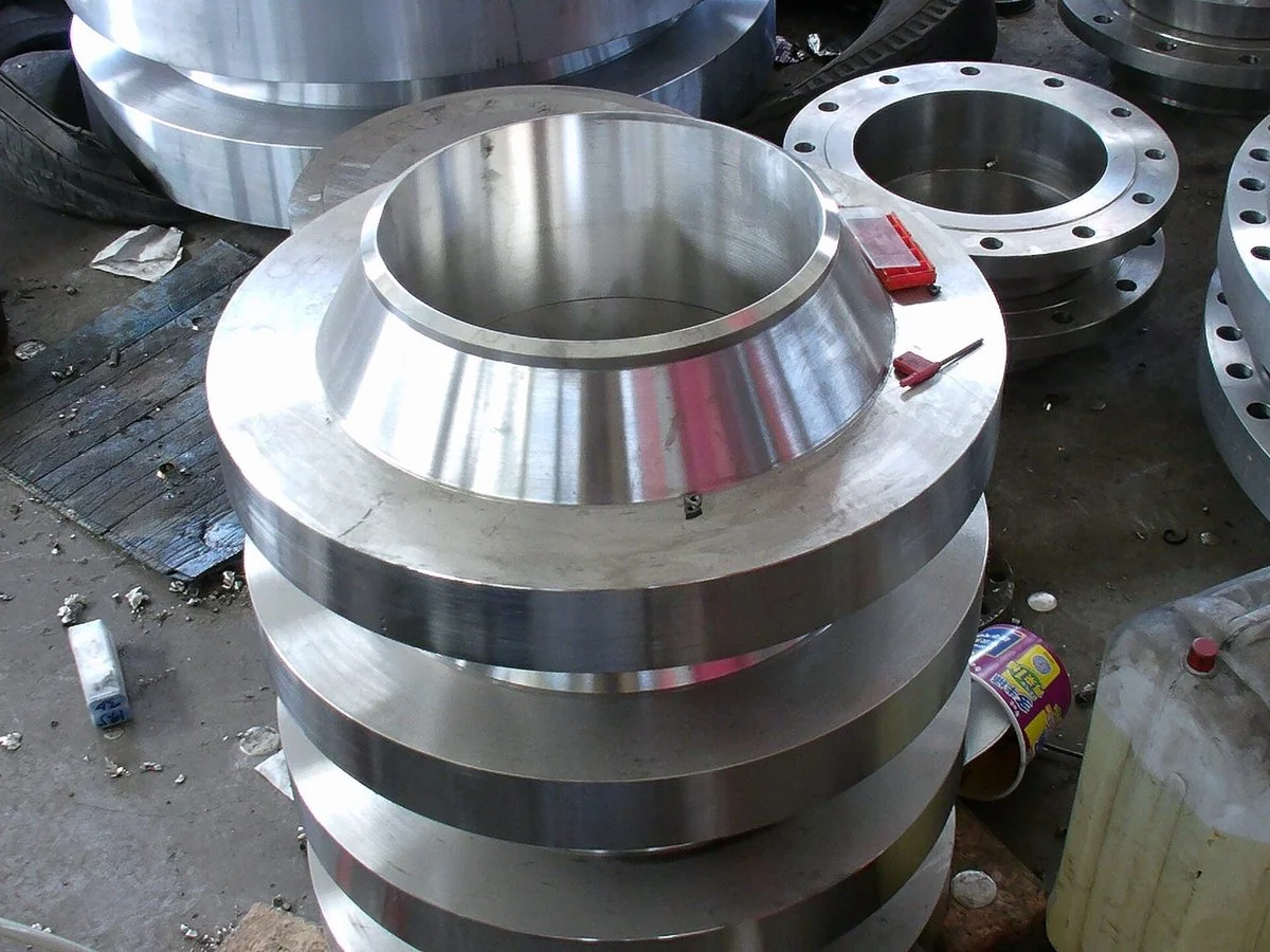
The machining photo below shows the bore and tapered hub. The sealing face is on the opposite side of the flange body; its geometry and finish must suit the gasket arrangement. Around the bore, the bolt holes sit on a defined bolt circle.
How the Butt-Welded Connection Works
The neck and pipe ends are aligned for butt welding. The applicable component standard and construction code determine the end preparation, fit-up, welding procedure and inspection requirements.
ASME B16.25 addresses butt-welding end preparation, including bevels and the internal and external shaping of heavy-wall components. Its applicability must be read together with the governing component requirements.
Internal pressure, temperature changes, bending and external forces all load the completed connection. The piping design must account for these loads, while fabrication controls the weld quality and alignment.
Raised Face, Flat Face, Ring-Type Joint and Male/Female Faces
“Weld neck” identifies the hub and pipe connection. The sealing face is specified separately:
| Facing | Basic arrangement |
|---|---|
| Raised face (RF) | A raised annular sealing surface surrounds the bore. The gasket bears on this defined area. |
| Flat face (FF) | The mating face is flat. The gasket arrangement must suit the joint design and mating equipment. |
| Ring-type joint (RTJ) | A machined groove receives a metal ring gasket of the specified profile and size. |
| Male and female (M/FM) | A projecting male face mates with a matching recessed female face, with the gasket seated between them. The mating dimensions and gasket must suit the applicable flange standard and joint design. |
Check the mating face and gasket before accepting a flange as compatible. An RTJ groove, for example, requires the specified metal ring gasket and mating groove; it cannot be substituted for a raised-face sealing surface.
Dimensions, Bore and Pipe Schedule
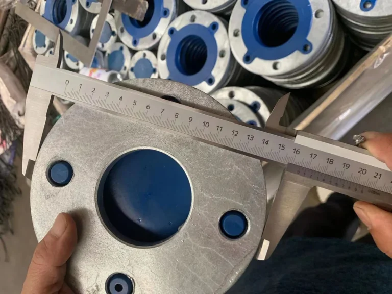
On a flange drawing, identify the outside diameter, body thickness, overall length through the hub, hub diameters, bore, bolt-circle diameter, and the number and diameter of bolt holes. Check the facing dimensions separately.
Nominal pipe size is a size designation. Pipe schedule relates to wall thickness under the relevant pipe dimensional standard. Two weld neck flanges with the same nominal size and pressure class can therefore need different bores or welding ends to suit different pipe walls.
Use the cross-section to locate the bore, body thickness and overall hub length. Read the drawing legend before using a dimension table: letter symbols vary between drawings.
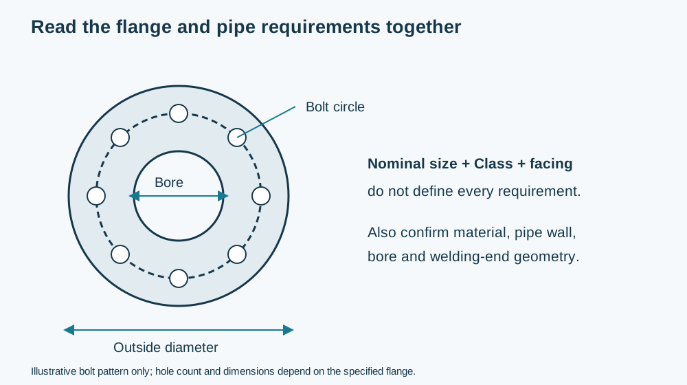
Specification example: “NPS 4, Class 150, RF, weld neck” identifies nominal size, class, facing and flange type. It does not complete the order: specify the material and grade, standard edition, connected pipe wall or bore, welding-end details and documentation requirements. This is a specification-reading example, not a dimensional or pressure-rating calculation.
| Feature | What to check |
|---|---|
| Outside diameter | Overall diameter of the circular flange body. |
| Body thickness and overall length | Use the measurement points shown on the drawing; these are different dimensions. |
| Bore and welding end | Coordinate with the connected pipe wall and specified joint detail. |
| Bolt circle and holes | Check the bolt-circle diameter, hole count and hole diameter together. |
| Facing | Confirm the sealing geometry and mating arrangement. |
Standards and Pressure-Temperature Ratings
ASME B16.5 covers pressure-temperature ratings, materials, dimensions, tolerances, marking and testing for pipe flanges and flanged fittings. Its flange scope includes Classes 150, 300, 400, 600, 900 and 1500 in sizes NPS ½ through NPS 24, and Class 2500 in sizes NPS ½ through NPS 12.
Class is a designation, not a pressure in psi. Read the pressure-temperature table for the applicable material group and operating temperature; Class 150 does not mean “150 psi.”
When comparing different standard systems, check the facing, bolt pattern, dimensions and rating rules together. A matching nominal size alone is insufficient.
Materials and Manufacturing
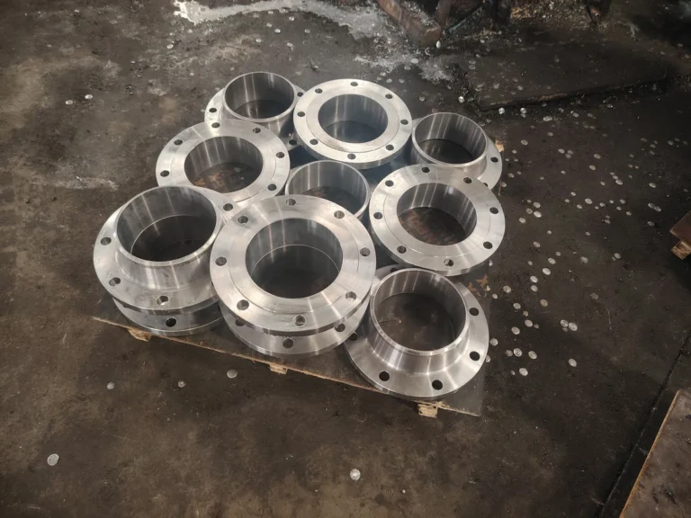
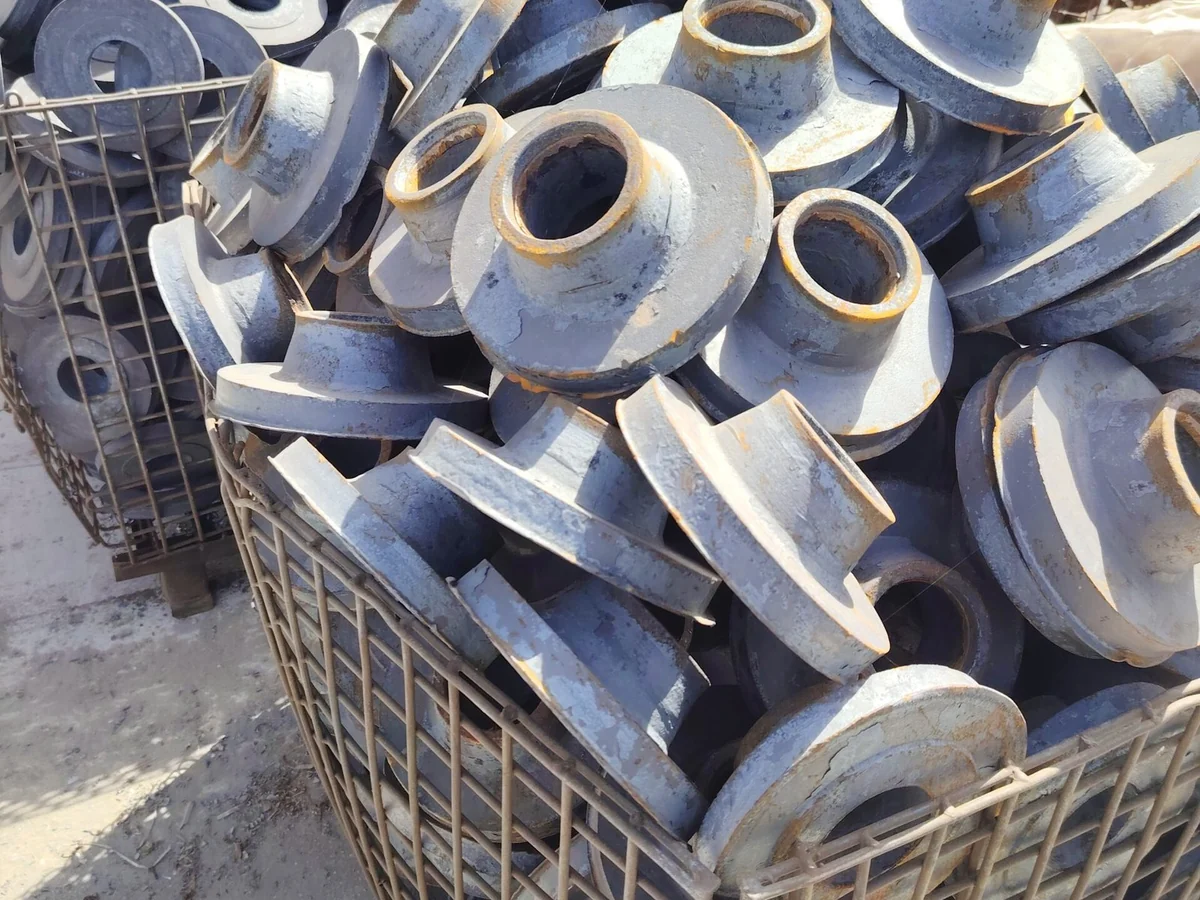
Weld neck flanges are commonly machined from forgings. Machining produces the bore, sealing face, bolt holes and welding end. The photo below shows blanks before finish machining, with rough surfaces and no drilled bolt holes.
ASTM A105/A105M covers carbon steel forgings for piping applications. ASTM A182/A182M includes alloy and stainless steel forged piping components, while ASTM A350/A350M covers carbon and low-alloy steel forgings requiring notch-toughness testing. These specifications serve different purposes; the full grade and material condition matter as well as the specification number.
Select the material grade for the service temperature, fluid, corrosion conditions and governing design requirements. The flange dimensional standard does not specify the grade on its own. The ASTM steel standards directory lists the material specifications. The individual links above refer to published editions used here to explain scope; the purchase specification should state the edition required by the project.
Standard and Long Weld Neck Designs
A standard weld neck flange has a tapered hub ending at the pipe weld. A long weld neck flange has an extended neck; its application and connection details should follow the governing standard or approved equipment drawing.
For a long weld neck design, specify the barrel profile, wall thickness, overall length, bore and end details. These features need their own dimensions rather than simply an added length on a standard weld neck flange.
A slip-on flange uses a different joint: the pipe enters its bore and is attached with fillet welds. Changing between slip-on and weld neck types changes the connection design.
Weld Neck Flange Weight
Finished weight depends on the body and hub geometry, bore, bolt holes, facing details and material density. Use these dimensions when estimating mass rather than nominal size and Class alone.
The weld neck flange weight calculator provides a way to estimate theoretical component weight from the tool’s dimensional and material inputs. Its drawing and units should be checked alongside the dimensions being evaluated.
Use theoretical weight for preliminary material and shipping estimates. Manufacturing tolerances and machining affect the measured finished weight, and shipment weight also includes packaging. Pressure ratings come from the applicable standard, not the weight calculation.
Before Ordering
- Flange type and nominal size.
- Applicable standard and edition.
- Class and facing.
- Material specification, grade and required condition.
- Connected pipe wall, schedule or specified bore.
- Welding-end details and approved drawing, where applicable.
- Quantity, inspection scope and documentation.
Before ordering, compare the flange bore and welding end with the pipe dimensions on the drawing. Include the mating face and gasket requirements in the same review.