
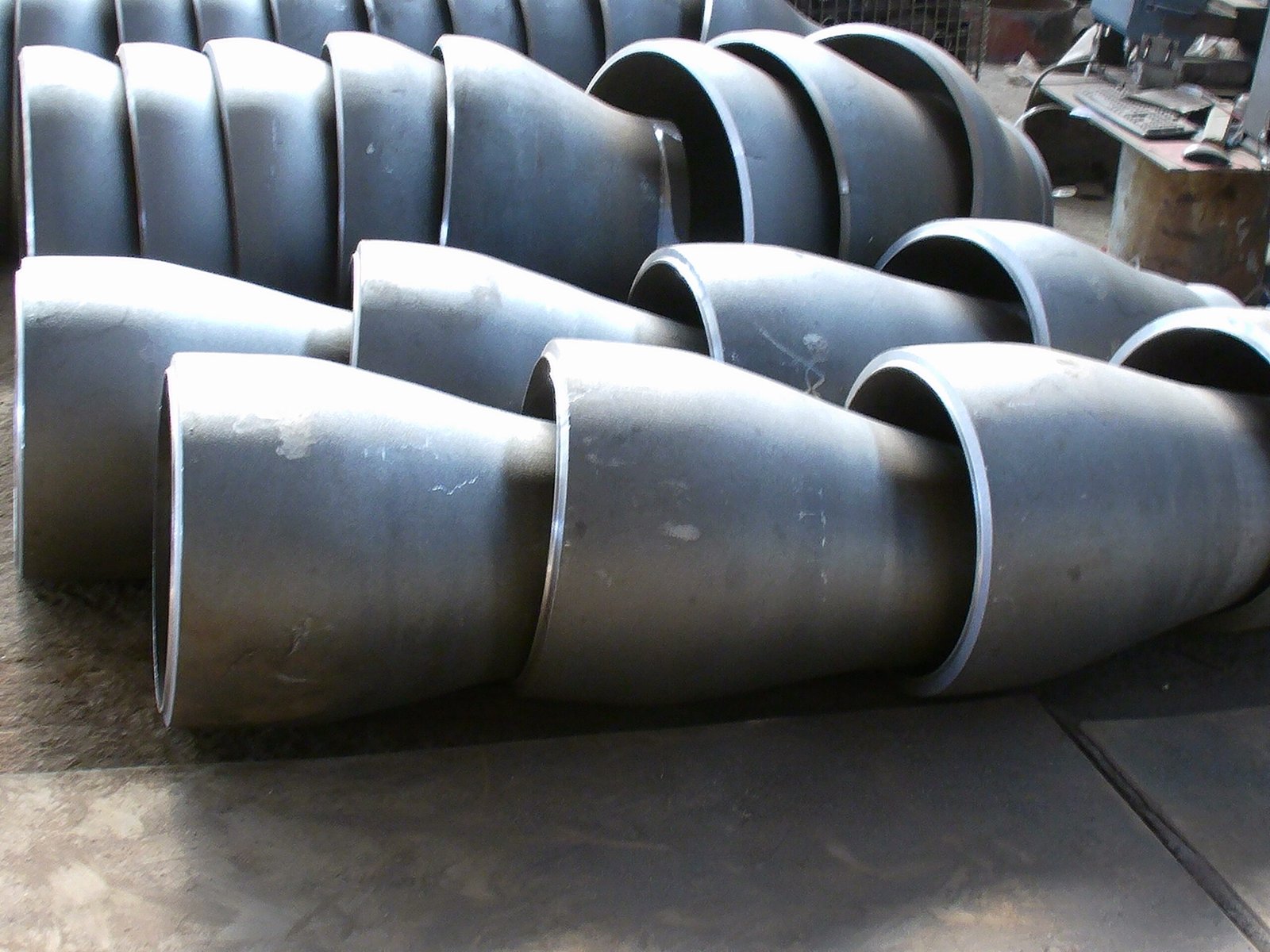
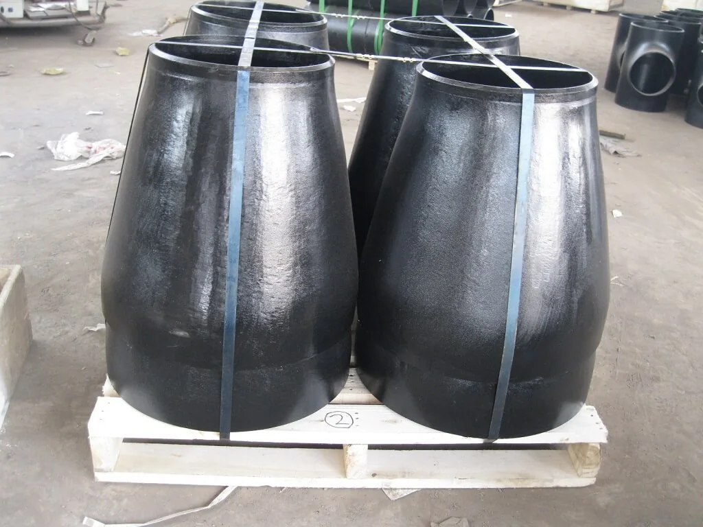
Concentric reducer
The two ends share a common centre line.
LEKE PIPING / PRODUCTS
Concentric reducers have a common centre line; eccentric reducers have an offset centre line. Specify both end sizes and wall thicknesses, plus eccentric orientation where required.
PRODUCT DETAILS
We can also make custom sizes, wall thicknesses and other dimensions to your drawing. Send the pipe-end requirements and your drawing with your RFQ so we can confirm the details.
| Parameter | Details to confirm |
|---|---|
| Type | Concentric or eccentric |
| End dimensions | Large-end and small-end outside diameters and end preparation |
| Wall | Wall thickness / schedule at each end |
| Geometry | End-to-end length and eccentric flat-side orientation, where applicable |
| Reference | Applicable fitting standard and edition, or drawing number and revision |
Product dimensions, material grades and documentation are confirmed against your enquiry and applicable project requirements.
Primary dimensional reference: ASME B16.9 (overall scope NPS 1/2–48; check the reducer table). Confirm the product type, edition and applicable size before order.
DIMENSIONAL REFERENCE
Use the section view to identify the dimensions to confirm in your enquiry.
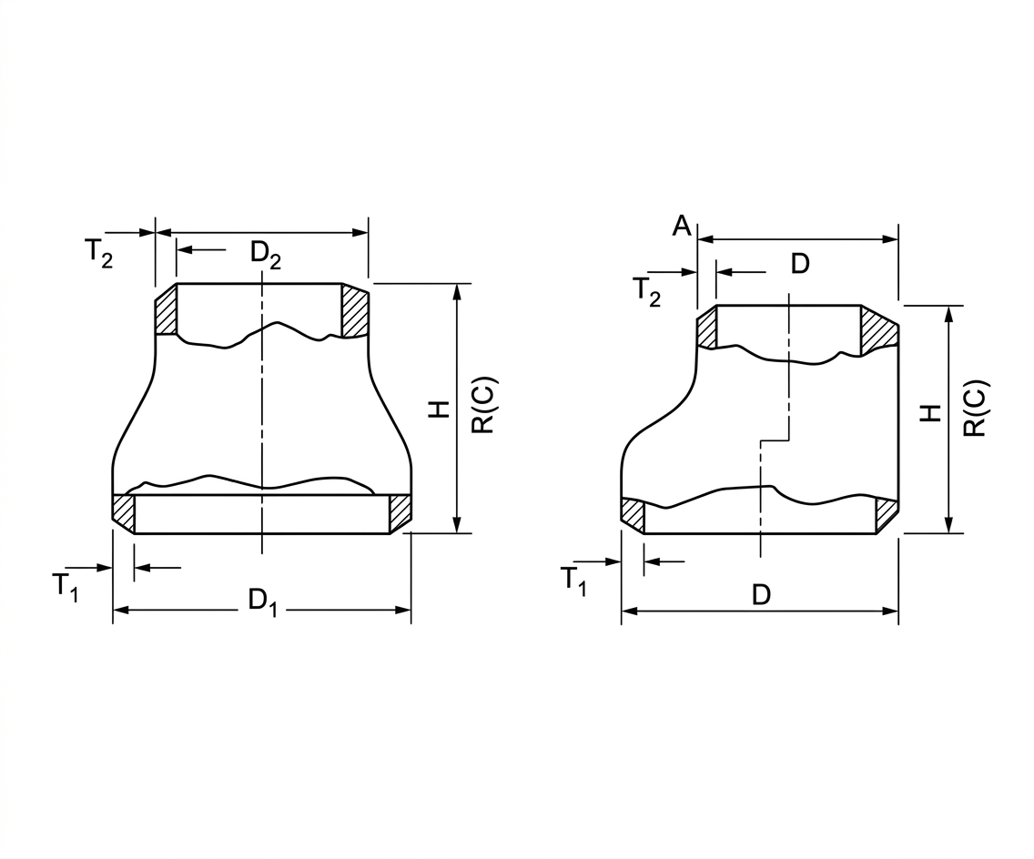
Views shown separately for legibility. The full original drawing remains available below.
View full-size drawing ↗Symbols describe this supplied drawing. Confirm their correspondence with the selected standard and dimension table; notation may differ.
Illustrative geometry only. Confirm size, wall thickness, dimensions, tolerances and the applicable standard edition in the selected table or approved drawing.
PRODUCT VIEWS
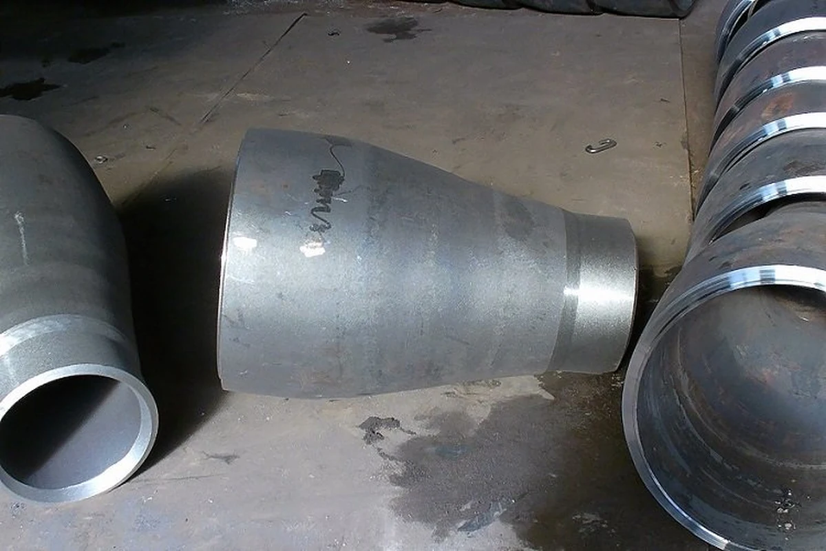
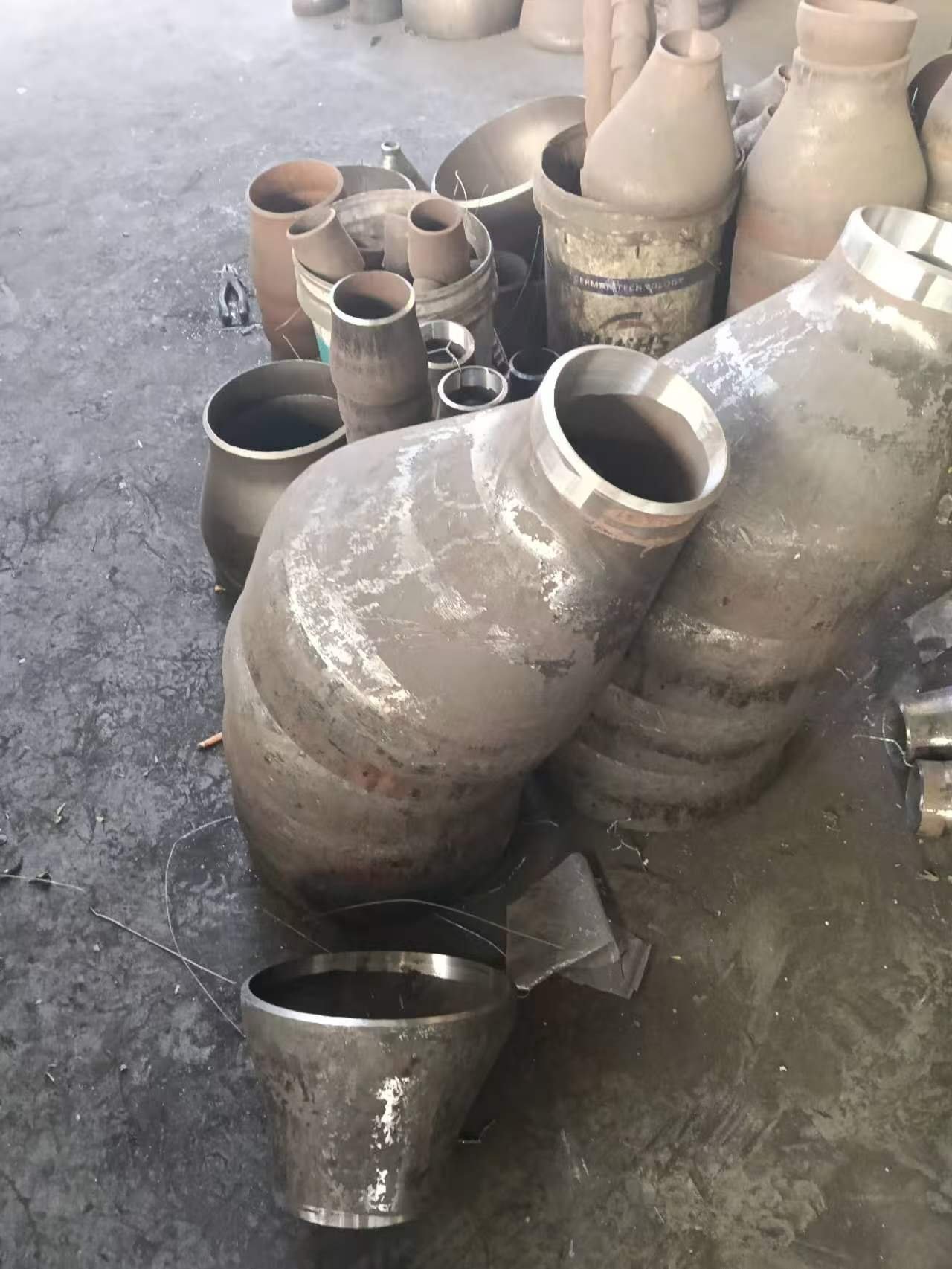
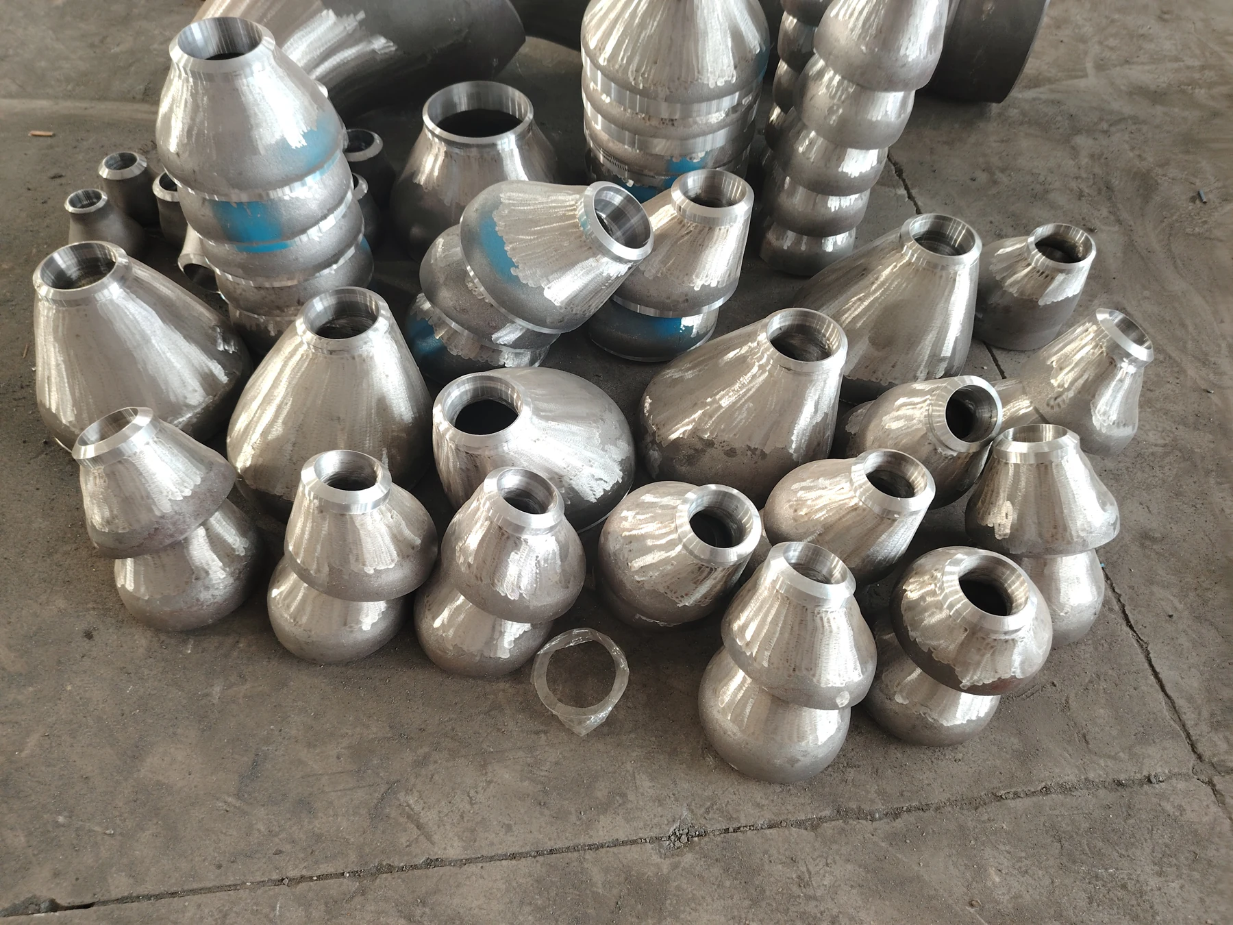
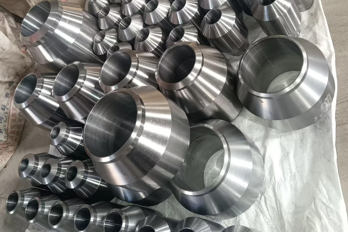
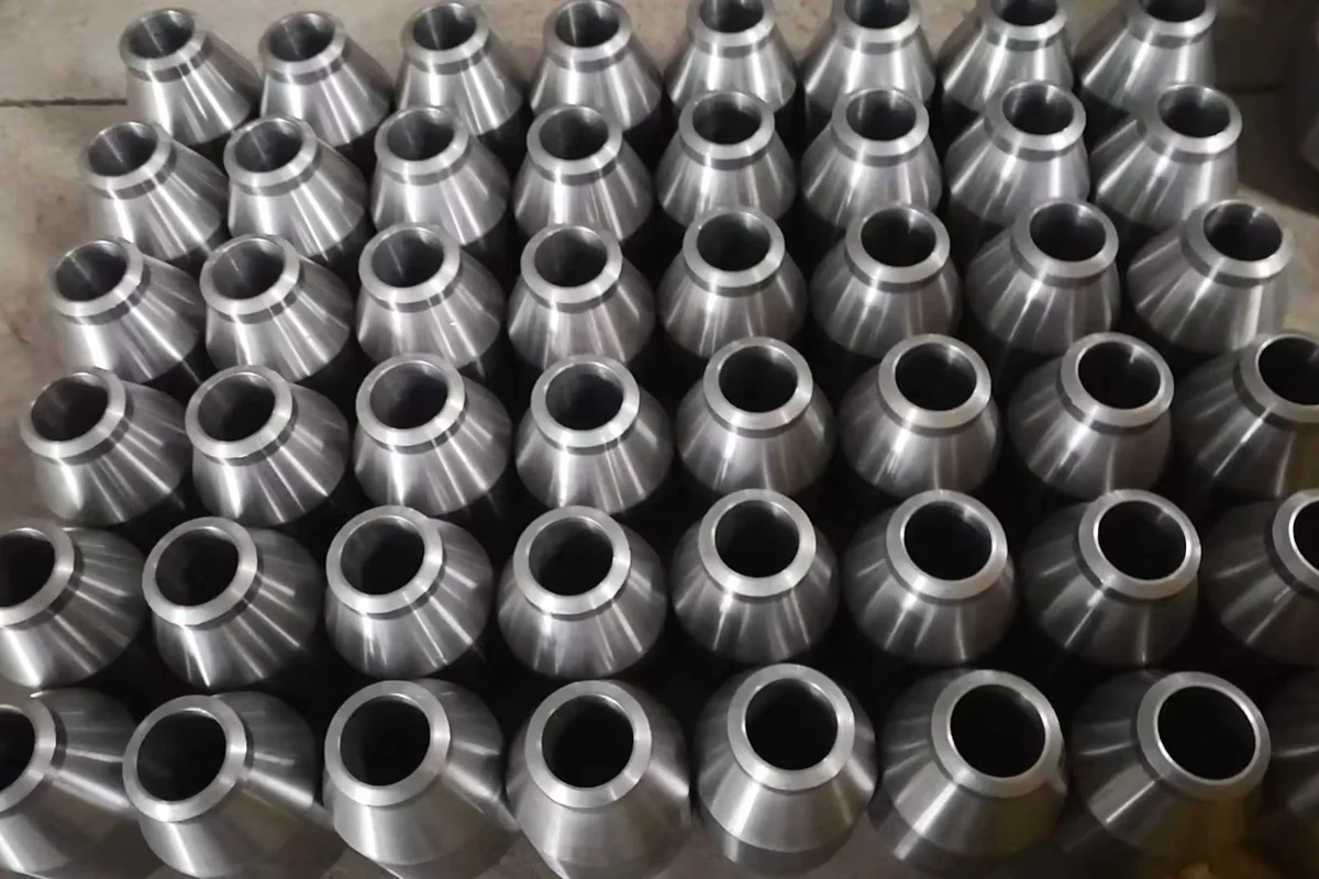
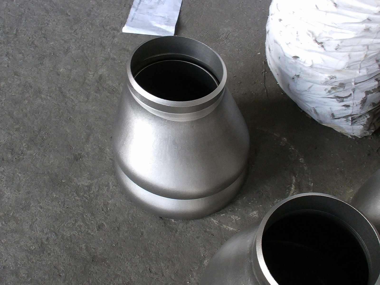
Compare the product views. Use the dimensional drawings and confirmed specifications for your order.
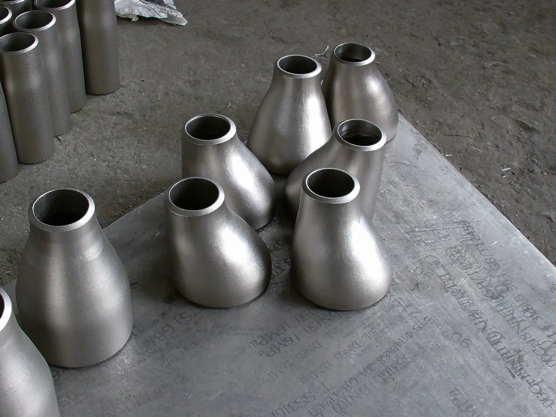
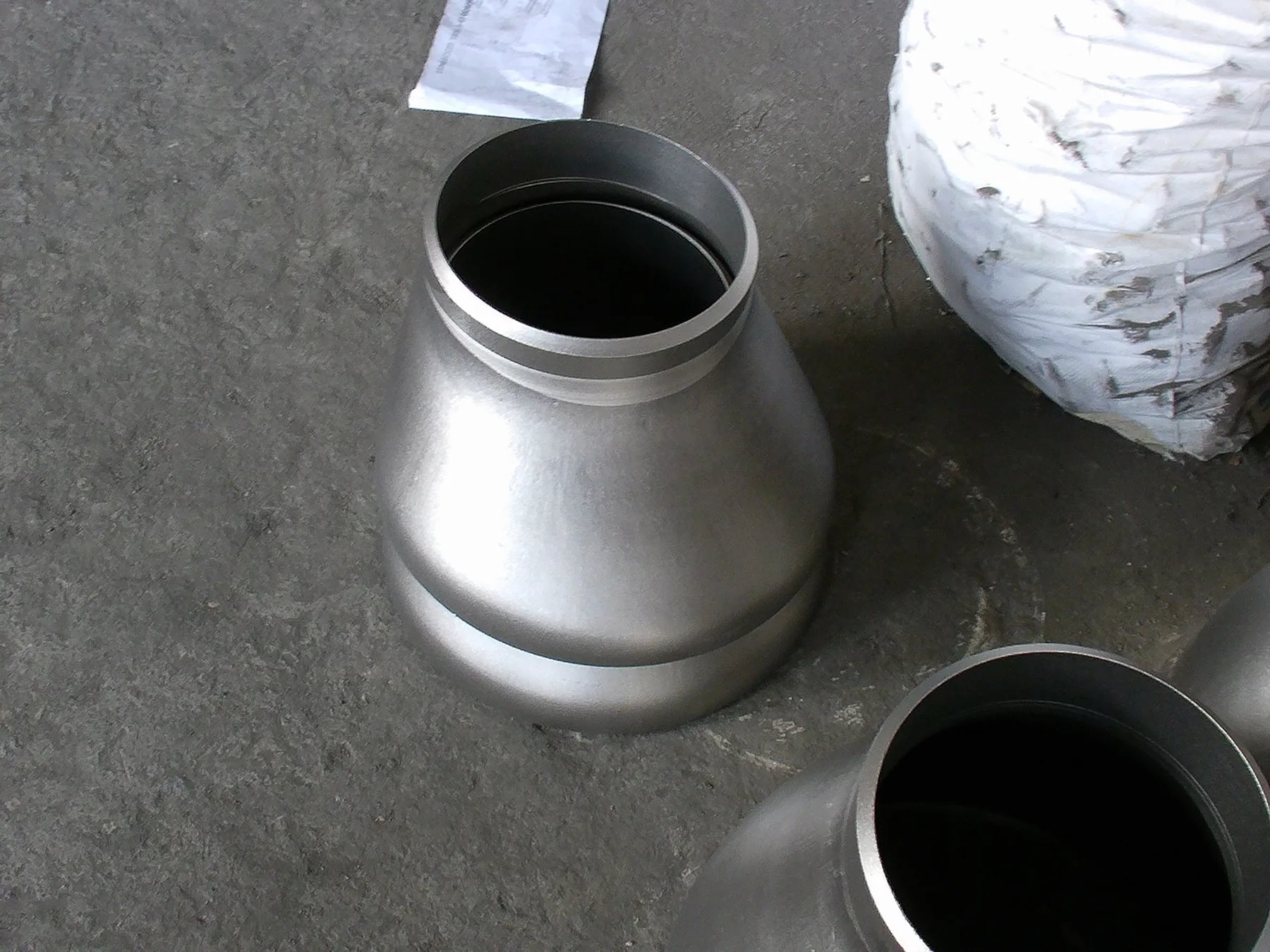
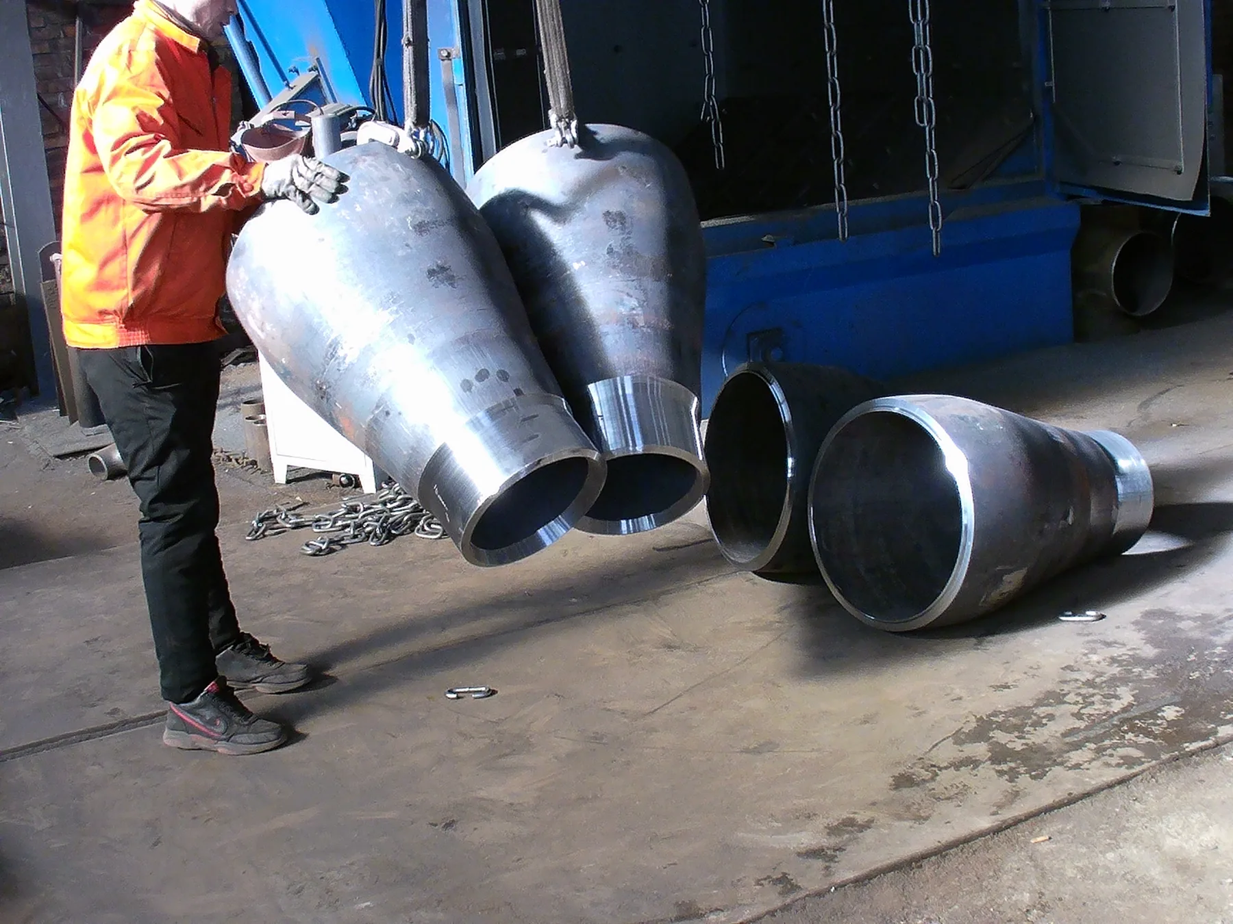
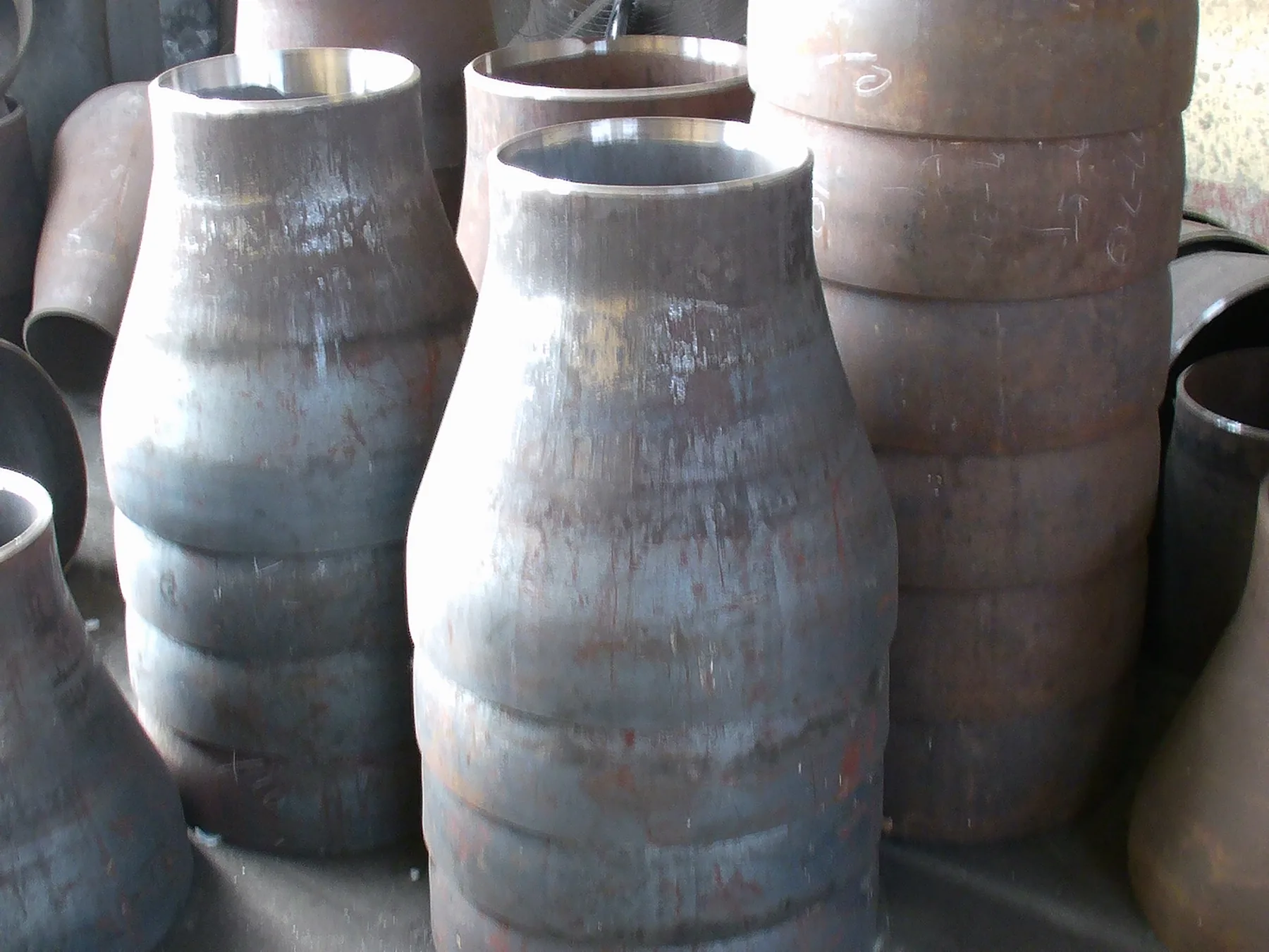
SELECTION & ENQUIRY
The two ends share a common centre line.
The centre lines are offset; show the required flat side and installation orientation on the drawing.
Specify each end outside diameter, wall thickness or Schedule, end preparation and end-to-end length.
TECHNICAL REFERENCES
ASME B16.9 — Reducer Dimensions
Check the applicable ASME B16.9 reducer table, edition, units and size range. Provide a dimensioned drawing and revision for non-standard geometry.
Use the existing calculator for preliminary estimates. Confirm the final dimensions, material and actual product weight separately.
COMMON QUESTIONS
The piping arrangement and project specification determine the configuration. Provide the layout or orientation requirement so the proposed reducer can be reviewed in context.
State the wall requirement at each end explicitly so the configuration and manufacturing requirements can be reviewed.
State the large-end and small-end sizes, the required wall at each end and the overall length. Identify concentric or eccentric geometry explicitly.
Show the required flat side and installation orientation on the piping or fabrication drawing. A product image alone does not define the installed position.
Nominal end sizes do not define all dimensions. Confirm actual end dimensions, wall requirements, length, material and the applicable specification.
No. A socket weld reducer insert and a butt weld pipe reducer have different connection geometry. Use the required connection description and a section drawing to identify the correct item.
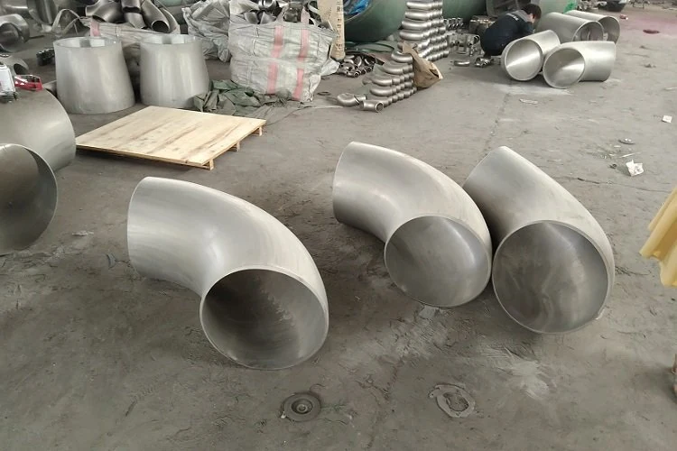 Pipe Elbows & Bends
Review the angle, radius and pipe-end requirements.
View product details →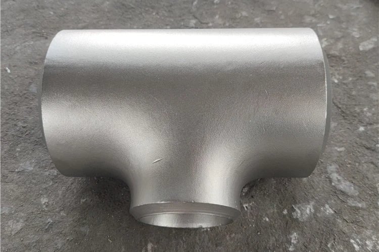 Equal & Reducing Pipe Tees
Review the run and branch sizes for your enquiry.
View product details →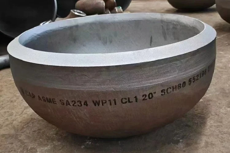 Butt Weld Pipe Caps
Review the end size, wall and closure dimensions.
View product details →Specify concentric or eccentric type, both end sizes and walls, length, material grade and quantity. Include the standard edition and drawing revision.
SEND YOUR REQUIREMENT
Email your reducer list with quantities, drawing revisions, destination and required date.
The quotation will confirm supply scope, required documents and delivery terms.